| Download |
An automated system for ensuring the reliability and the quality of the equipment (ASONIKA)
A.Shalumov, 2017
General Director of "ASONIKA" Scientific-Research Institute, Professor, Dr.,
Head of development ASONIKA system
www.asonika.com
________________________
Abstract: The article discusses outcomes and further development of an automated system for ensuring reliability and quality of the equipment ASONIKA.
Keywords: radio electronic means, modeling, radio-frequency components, mechanical effects, thermal effects.
An automated system for ensuring reliability and quality of the equipment (ASONIKA) can help realize computer-aided design and an integrated computer simulation of highly reliable radio electronic means (REM) of moving objects in accordance with the requirements of CALS-technologies at the stages of engineering-production-exploitation.
Operation of onboard REM is characterized by combination of rigid external factors that act simultaneously, which leads to a systemic failure. During testing, such failures are difficult to detect since there are no stands that would allow to fully recreate simultaneously electrical functioning processes, the accompanying thermal, mechanical, aerodynamic, radiation and other environmental effects, technological effects of random variation parameters, aging, corrosion and other degradation factors. The problem is complicated by the fact that modern REM include advanced microelectronic products with certain physical and technological features, which should also be considered in the complex mathematical modeling. All of these factors and interrelated effects must be properly taken into account during the technological engineering that can only be performed by a computer. In this case, the causes of system failures can really be pre-identified and eliminated and high reliability of the REM is provided.
ASONIKA is designed to solve four major problems existing in the development of modern REM:
- The problems of preventing possible failures during the operation in the early stages of engineering due to the complex modeling of heterogeneous physical processes;
- The problems of human safety when flying on airplanes (prevention of crashes) due to complex automated analysis system based on the control of the aircraft created an electronic model for all types of external destabilizing factors, including those in critical conditions;
- The problems of reducing time and costs of the engineering due to availability of equipment offered to a developer by software and the adequacy of the modeling results;
- The problem of automating workflow, and creating an electronic model of a product offered by the integration of software tools within the PDM-system storage and management of engineering data and product lifecycle management (equipment).
ASONIKA - Russia's first automated system for complex modeling of physical processes in the electronic equipment that is recommended to replace the testing of electronic equipment modeling in the early stages of engineering, which allows you to create competitive equipment in the shortest possible time and with minimal costs.
The developer of the system ASONIKA is "Scientific school of modeling, information technology and automated systems". The founder and leader of the scientific school is Prof. A. Shalumov. The basic principle of the scientific school - unity of 4 components: Education - Science - Manufacturing - Business. Scientific school has published over 300 books, manuals and articles.
ASONIKA has no analogues In Russian Federation. The information about any foreign analogues is missing from the press.
ASONIKA system is used in many Russian companies that are developing electronic devices. Use of ASONIKA in the engineering and the technical expertise of prototype electronic means allows to reduce the complexity of the project research (in some cases up to 35-40%), improve the quality of the samples (above all - their reliability because of early detection and elimination of preconditions to failure, associated with the irrational schematic and engineering decisions), cost savings by reducing the amount of work needed to create and to study the models, reduce the volume of all types of tests (up to 10-15%).
The methodological basis for solving assigned tasks is developed scientific principles of mathematical field modeling theory and processes of different physical nature, interacting with each other in a single heterogeneous environment, and system methods of sensitivity theory.
Within the automated system ASONIKA, special software package is implemented that creates the electronic (virtual) structure of developed REM layout, which fills this structure with results of problematic subsystems (subsystems can simulate the thermal and mechanical processes in equipment, analyze the reliability, and also allow integration with known systems of the topological design of printed circuit boards and known CAD-systems).
The software package controls the display of model experiments results on the geometric model, which is part of the electronic layout, and also converts the electronic layout after it is processed into ISO 10303 STEP format. The data included in the electronic model is used in later stages of the REM’s life cycle.
The ASONIKA system currently consists of 8 subsystems:
- Subsystem analysis of the mechanical effects on the REM three-dimensional structures - ASONIKA-M;
- Subsystem analysis and resistance to mechanical damage of the REM structures, installed on vibration isolators - ASONIKA-V;
- Subsystem analysis and thermal characteristics of the equipment structures - ASONIKA-T;
- Subsystem analysis of thermal and mechanical effects on REM printed circuit assemblies structures - ASONIKA-TM;
- Subsystem of automated filling cards of the radio-frequency component (RFC) operating modes - ASONIKA-P;
- Subsystem of REM reliability analysis based on actual RFC modes - ASONIKA-B;
- Radio-frequency components and materials reference database on the geometrical, physical, mechanical, thermal, and electrical reliability parameters - ASONIKA-DB;
- Subsystem of REM modeling management during engineering - ASONIKA-UM.
- ASONIKA system includes the following converters with known CAD:
The system modeling integration module of electrical processes in PSpice (as part of OrCAD) and subsystems ASONIKA-P, ASONIKA-B (module integration with systems such as Mentor Graphics, Altium Designere is under development);
System integration module of PCAD, Mentor Graphics, Altium Designere, OrCAD printed circuit assembly engineering and ASONIKA-TM subsystem;
3-D model integration module created in the systems such as ProEngineer, SolidWorks, Inventor and other IGES and STEP file formats and ASONIKA-M subsystem.
The development of RECs electromagnetic compatibility subsystem is under way - ASONIKA - EMC and possible development of REM radiation resistance subsystem – ASONIKA - RAD.
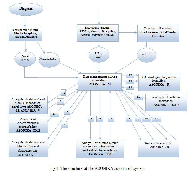
The structure of the automated system ASONIKA (Fig. 1) provides that in the design process, in accordance with the requirements of CALS-technologies, based on the subsystem data management during modeling ASONIKA-UM (PDM-systems) and with using simulation subsystems, the formation of electronic model products occurs.
With the help of a special graphics editor, electrical circuit is introduced, which is stored in a subsystem ASONIKA-UM project database and is sent as a file to the analysis system of electrical circuits PSpice (OrCAD), Mentor Graphics and Altium Designere and to the system placement and routing of printed circuit boards PCAD, Mentor Graphics, Altium Designere, OrCAD. PCAD system output files (in the PDIF format) and Mentor Graphics, Altium Designere, OrCAD (in the IDF format) are stored in the ASONIKA-UM subsystem. They are sent to the systems such as ProEngineer, SolidWorks, Inventor and others for creating schematics and saved in the ASONIKA-UM subsystem. 3-D models of REM cabinets and blocks, created in the systems such as ProEngineer, SolidWorks, Inventor and others (file formats IGES and STEP) can be also sent to the ASONIKA-UM subsystem, which are sent from it to the subsystem ASONIKA-M and ASONIKA-V (1) to analyze mechanical processes in REM cabinets and blocks, in the subsystem ASONIKA-T (3) and to analyze thermal processes in REM cabinets and blocks. As a result of simulation, stress, displacement, acceleration and temperature in cabinets and the blocks structures are stored in the ASONIKA-UM subsystem (2, 4). Printed circuit assembly blueprints and specifications for them, as well as files in the PDIF and IDF formats transferred from the ASONIKA-UM subsystem into the ASONIKA-TM subsystem (5) for a comprehensive analysis of thermal and mechanical processes in printed circuit assembly. In addition, the temperatures in the nodes are sent, which are obtained in the subsystem ASONIKA-T, as well as acceleration support received in the ASONIKA-M subsystem (6). Received as a result of a simulation, RFC temperature and acceleration are saved in the ASONIKA-UM subsystem (7). RFC list (8), files with the RFC electrical characteristics (9), RFC temperatures and accelerations (10), the results of the electromagnetic (15) and radiation (16) analysis obtained in ASONIKA-EMC and ASONIKA-RAD subsystems are transferred from the ASONIKA-UM subsystem into ASONIKA - B (analysis reliability subsystem). Received as a result REM reliability indexes are saved in the ASONIKA-UM subsystem (11). RFC list, files with the RFC electrical characteristics (12), RFC temperatures and accelerations (13) are sent from the ASONIKA-UM subsystem into the ASONIKA - R subsystem (subsystem of operating modes card formation). Received as a result maps of the operating modes are saved in ASONIKA-UM the subsystem (14).
The system is aimed at the REM developers. With this purpose in the ASONIKA-M and ASONIKA-TM subsystems, special interfaces have been developed for input of standard structural equipment such as cabinets, blocks, printed circuit assemblies, which greatly simplify the analysis of physical processes in the REM.
If a user is building a model of a complex cabinet’s or block’s mechanical processes (see Fig. 2, 3) in the usual finite-element system, for example, ANSYS, he would have to first undergo special training and gain experience that would take about a year, and then for a few hours enter the model. You do not need to undergo special training in ASONIKA system; you just need to enter in accessible constructor language that is represented in the diagram. Entering the same complex cabinet can be carried out within an hour.
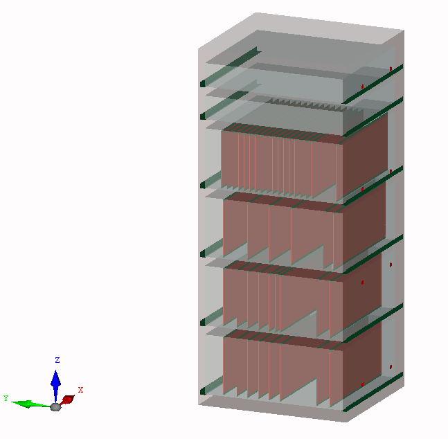
Fig.2. Model design a 6-storey cabinet (KB IGAS "Wave"),
entered in the ASONIKA-M subsystem
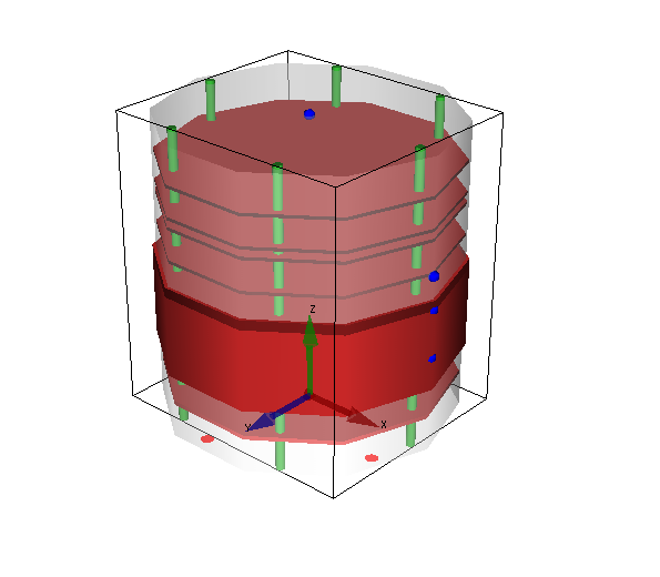
Fig.3. The model design of a cylindrical type block (State Research Institute of Instrument Engineering)entered)
in ASONIKA-M subsystem
Thus, a full comprehensive analysis of the cabinet on the thermal and mechanical effects for each RFC (we get acceleration and temperature for each element) can be completed within one day.
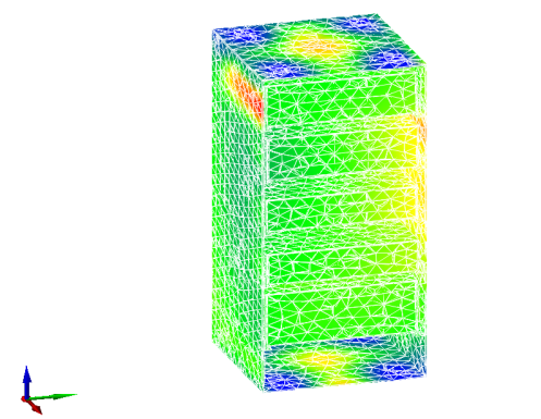
Fig.4. The maximum values of stress in the construction of
cabinet when subjected to a single mechanical impact.
Fig.5. Acceleration and deformation of block’s construction sites
obtained in the ASONIKA-M subsystem
ASONIKA-M (subsystem analysis of volumetric REM structures on the mechanical effects) allows the analyzing of the cassette, the cordwood and the cylindrical type blocks, cabinets, and radio electronic means and to carry out calculations of the following types of mechanical effects:
- harmonic oscillation;
- random oscillation;
- impact;
- linear acceleration.
As a result of simulation, we can obtain:
Acceleration dependence on the frequency and the time at the checkpoints and structure nodes;
displacement, deflection, acceleration and strain of the construction block sites and cabinets (Fig. 4, 5);
The deformation of blocks and cabinets (Fig. 5);
The acceleration at printed circuit assemblies fastening points required for further analysis up to each REM in the ASONIKA-TM subsystem.
ASONIKA-B (subsystem analysis and ensuring resistance to mechanical effects of REM structures installed on vibration isolators) is designed to analyze the mechanical characteristics of the REM cabinets, racks and blocks structures, installed on vibration isolators, under the influence of harmonic oscillation, random oscillation, shock loads, linear acceleration, with effects of acoustic noises and for making a decision on the basis of the mechanical characteristics in order to ensure the stability of the equipment under mechanical loads. The subsystem has a special graphical user interface for structure on vibration isolators input.
The subsystem allows for the identification of the vibration isolators parameters, as well as the optimization of their parameters in order to reduce structural loads. As a result of simulation, structure acceleration on vibration isolator’s dependence on the frequency and the time can be obtained.
ASONIKA-T (subsystem analysis and thermal characteristics of REM structures) allows us to analyze the following types of structures: micro assembly, radiators and heat sinking bases, hybrid-integrated modules, cordwood blocks and cassette structures, cabinets, racks, as well as arbitrary REM structures.
The subsystem allows you to analyze the stationary and nonstationary thermal conditions of the equipment, operating at the natural and forced air convection, both at normal and at reduced pressure.
During the analysis of arbitrary structures, selected isothermal volume temperatures are determined and graphics are displayed of temperature dependence on time for nonstationary thermal conditions.
ASONIKA-TM (subsystem analysis of REM printed circuit assembly structures on thermal and mechanical effects) allows you to analyze REM printed circuit assembly and to calculate:
stationary and nonstationary thermal conditions both at normal and at reduced pressure;
the following types of mechanical impact:
- harmonic oscillation;
- random oscillation;
- impact;
- linear acceleration;
- acoustic noise.
The subsystem has a special graphical user interface for structural printed circuit assembly input.
As a result of a simulation, we can be obtained:
Acceleration dependence on the frequency and the time at the checkpoints and structure nodes;
Maximum temperatures, acceleration, and stress areas on printed circuit assemblies and radio-frequency components (Fig. 7,8,9);
The vibration modes of printed circuit assemblies on their own frequencies;
Radio-frequency components’ maps of thermal and mechanical modes.
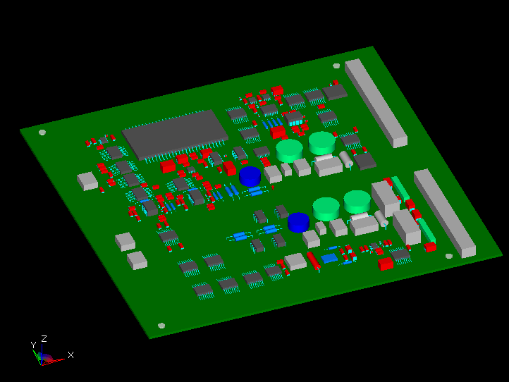
Fig.6. Printed circuit board assembly design
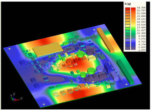
Fig.7. Acceleration field on the 1st resonance frequency at normal temperature
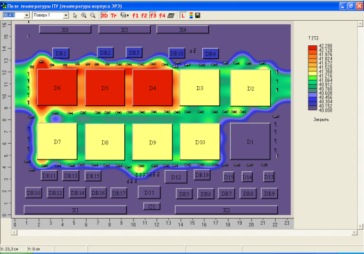
Fig.8. The temperature field in the circuit board
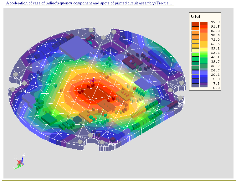
Fig.9. Acceleration field on the 1st resonance
frequency, taking into account the temperature
ASONIKA-B (subsystem REM analysis and reliability) allows you to analyze cabinets, power, printing nodes, RFC and perform the following tasks: 1) determination of reliability of RFC; 2) justification for and evaluation of reservation REM. The subsystem supports: 1) The passive reservation with a constant load; 2) actively loaded reservation; 3) active unloaded reservation; 4) actively facilitated reservations. As a result of simulation, we can obtain: the operational failure rate, the probability of failure-free operation and REM mean time between failures. The subsystem allows you to import data structures from other computer-aided design (CAD) systems. The subsystem allows you to import RFC thermal and electrical characteristics from other ASONIKA subsystems.
Supplemental data base radio-frequency components (RFC) and the materials on the geometrical, physical, mechanical, thermal, and electrical reliability parameters - ASONIKA-DB provides information: 1) the parameters of materials, 2) the parameters RFC. ASONIKA-DB consists of main and supplementary tables. The main tables contain the following information:
The material parameters of the printed circuit assemblies, load-bearing structures, the RFC output and varnishes (adhesives) used in the installation RFC on the circuit boards: mechanical, thermal, admissible, the temperature dependence;
The optical properties of radio-frequency component construction;
RFC parameters: RFC classes and groups; types of RFC and specifications; full conditional entries of RFC; the parameters in the full conditional entry and their possible values; the installation options RFC on the printed circuit board; RFC model installation options; RFC geometric, mechanical, thermal, electrical, reliable, available options, RFC images on a plane and in space;
The mathematical model for calculating the values of the RFC operational failure and the coefficients values of the reliability model;
The vibration isolators parameters: the coefficients of stiffness, damping, and etc.
Additional tables are created. Additional tables can contain numeric, string, logical, text, graphics and functionality dependency parameters of the RFC.
ASONIKA-UM (subsystem management modeling during the REM engineering) allows for integration of CAD, embedded in the companies - Pro / ENGINEER, SolidWorks, Inventor, Mentor Graphics, Altium Designere, OrCAD, ASONIKA and etc., and manages data transfer between the subsystems during modeling in the process of REM structural engineering. The subsystem integrates with any PDM-system used in the company. During engineering, the subsystem allows to generate a comprehensive model of REM within mathematical models of thermal, electrical, aerodynamic, mechanical processes and mathematical models of REM reliability and quality.
Realization of the described integration marked the beginning of the development and implementation of CALS-technologies in the companies of electronic and instrument industries. Practical and innovative results are as follows. Integration software allows REM composite computer-aided design, based on simulation of complex physical processes. Language of user interface with software is as close as possible to the language of REM developer. The familiarization with the proposed programs requires a relatively short time. When implemented, a sufficiently high rate of modeling problem solving and significant savings of material means is attained by reducing the number of tests. Increased REM reliability and quality, engineered on the basis of the proposed integrated CAD.
Information consistency of the whole system provided at a level REM electronic model, in which information is represented as a set of information objects and relationships between them, regulated by ISO 10303 STEP, with no duplication of information. In this case, there is a need only in the interfaces between each individual subsystem and ASONIKA-UM subsystem.
These interfaces provide conversion of REM information objects electronic model, describing the original data for the target subsystem, in the project files of the subsystem and vice versa - converting project files of the original subsystem in REM information objects electronic model and their interactions, regulated by ISO 10303 STEP, providing unambiguous presentation of information in an electronic model of REM.
This solution of the information consistency provides the flexibility of REM ASONIKA’s system structure. Thus, during the update, replacement of existing subsystems, and the addition of new subsystems in this structure, it is necessary to change the interfaces of integration with the ASONIKA-UM subsystem that needed to be replaced or introduced into the structure. Complexity of the interfaces is defined by used as components through CAD REM software systems.
The purpose of application of the ASONIKA system is to increase the efficiency of the structural units of the company, to shorten engineering and development time of highly technological REM, and to increase reliability developed REM.
Thus, the application of the ASONIKA system will be your transition to a new level of information technology that will expand the range of products, reduce time it takes a new product to the market, reduce the number of defects and the production costs.
Suggestion:
1. The application of ASONIKA in the electronics industry companies and in universities.
2. To provide consulting services to electronic industry companies with modeling of electronic equipment on the exterior mechanical, thermal, electromagnetic and other effects with the help of ASONIKA.
3. To organize the training of specialists for working with ASONIKA system.